MBI5027 with Arduino to verify everything is setup correctly

Ok, so I built a bunch of Snoodles back in the day, but they require a parallel port on a computer to use them. Believe it or not, parallel ports aren’t exactly abundant these days. To resolve the issue of having a pile of Snoodles that can’t be used on a standard computer, I turned to setting up an Arduino provide a USB interface for the Snoodles. Because nothing ever works the first time you try it, after all my troubleshooting, I decided to write this up because I had to relearn how to use an MBI5027 shift register. Basically, I read the datasheet 10 times, still had struggles, and turned to the http://doityourselfchristmas.com forums for guidance.
Main learning points:
- Terminal description on the MBI5027 datasheet sucks and the timing diagram is correct (in reference to the latch state)
- Pin 21 requires it is grounded. Not that the datasheet says otherwise, I just didn’t notice it on my Snoodle PCBs because it was under the MBI5027 socket
- Pin 23 requires it is grounded, either with or without a resistor. My Snoodle PCBs use a 1.5k resistor to control the current, but my prototype (as well as the Grinch PCB traces) have it tied directly to ground without a resistor
Arduino code:
Pin 5 on the Arduino is configured as an output and connected to the SDI (pin 2) on the MBI5027
Pin 6 on the Arduino is configured as an output and connected to the CLK (pin 3) on the MBI5027
Pin 7 on the Arduino is configured as an output and connected to the LE(ED1) (pin 4) on the MBI5027
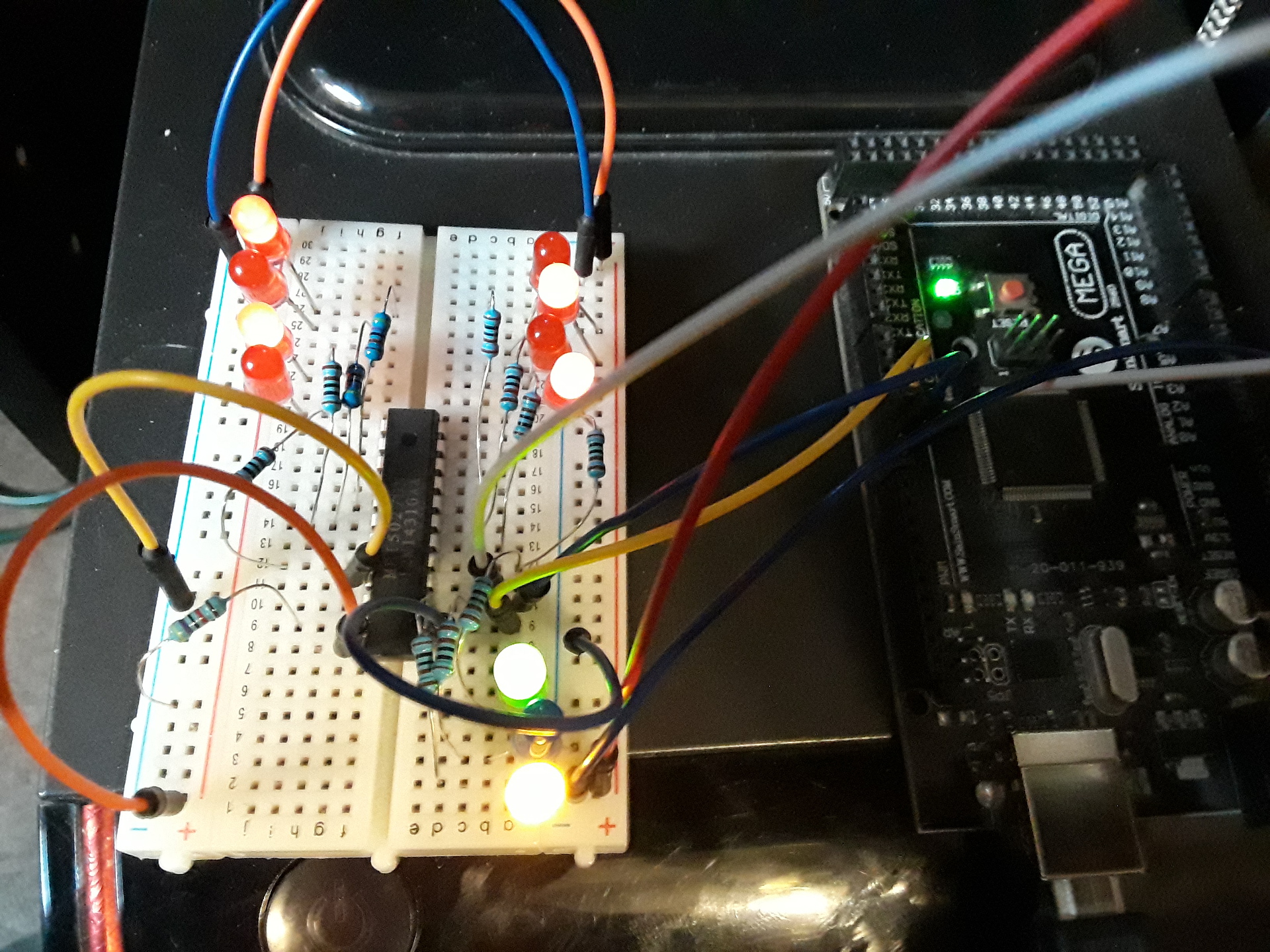
During troubleshooting, I connected a yellow LED to the SDI pin, a blue LED to the clock, and a green LED to the latch. This allows for visual observation of exactly what data is being sent to the individual MBI5027 pins. This will also help troubleshoot if the Arduino outputs aren’t working at all. Depending on the version of your Arduino (Uno/Mega, etc), sometimes the define pins don’t match. If you don’t see the LEDs flashing/solid, you will know they are not getting any HIGHs and can begin there.
void setup() {
// initialize digital pin 13 as an output.
pinMode(5, OUTPUT); //SDI (2) Yellow
pinMode(6, OUTPUT); // Clock (3) Blue
pinMode(7, OUTPUT); //Latch (4) Green
}
// the loop function runs over and over again forever
void loop() {
digitalWrite(7, LOW); // Latch
digitalWrite(5, LOW); // SDI Low
delay(17);
digitalWrite(6, HIGH); // 1st bit
delay(17);
digitalWrite(6, LOW);
delay(17);
digitalWrite(5, HIGH); // SDI High
digitalWrite(6, HIGH); // 2nd bit
delay(17);
digitalWrite(6, LOW);
delay(17);
digitalWrite(5, LOW); // SDI Low
digitalWrite(6, HIGH); // 3rd bit
delay(17);
digitalWrite(6, LOW);
delay(17);
digitalWrite(5, HIGH); // SDI High
digitalWrite(6, HIGH); // 4th bit
delay(17);
digitalWrite(6, LOW);
delay(17);
digitalWrite(5, LOW); // SDI Low
digitalWrite(6, HIGH); // 5th bit
delay(17);
digitalWrite(6, LOW);
delay(17);
digitalWrite(5, HIGH); // SDI High
digitalWrite(6, HIGH); // 6th bit
delay(17);
digitalWrite(6, LOW);
delay(17);
digitalWrite(5, LOW); // SDI Low
digitalWrite(6, HIGH); // 6th bit
delay(17);
digitalWrite(6, LOW);
delay(17);
digitalWrite(5, HIGH); // SDI High
digitalWrite(6, HIGH); // 8th bit
delay(17);
digitalWrite(6, LOW);
delay(17);
digitalWrite(5, LOW); // SDI Low
digitalWrite(6, HIGH); // 9th bit
delay(17);
digitalWrite(6, LOW);
delay(17);
digitalWrite(5, HIGH); // SDI High
digitalWrite(6, HIGH); // 10th bit
delay(17);
digitalWrite(6, LOW);
delay(17);
digitalWrite(5, LOW); // SDI Low
digitalWrite(6, HIGH); // 11th bit
delay(17);
digitalWrite(6, LOW);
delay(17);
digitalWrite(5, HIGH); // SDI High
digitalWrite(6, HIGH); // 12th bit
delay(17);
digitalWrite(6, LOW);
delay(17);
digitalWrite(5, LOW); // SDI Low
digitalWrite(6, HIGH); // 13th bit
delay(17);
digitalWrite(6, LOW);
delay(17);
digitalWrite(5, HIGH); // SDI High
digitalWrite(6, HIGH); // 14th bit
delay(17);
digitalWrite(6, LOW);
delay(17);
digitalWrite(5, LOW); // SDI Low
digitalWrite(6, HIGH); // 15th bit
delay(17);
digitalWrite(6, LOW);
delay(17);
digitalWrite(5, HIGH); //SDI HIGH
digitalWrite(6, HIGH); // 16th bit
delay(17);
digitalWrite(6, LOW);
delay(17);
digitalWrite(7, HIGH); // LATCH!
delay(3000);
digitalWrite(7, LOW); // Latch
digitalWrite(5, HIGH); // SDI High
delay(17);
digitalWrite(6, HIGH); // 1st bit
delay(17);
digitalWrite(6, LOW);
delay(17);
digitalWrite(5, LOW); // SDI Low
digitalWrite(6, HIGH); // 2nd bit
delay(17);
digitalWrite(6, LOW);
delay(17);
digitalWrite(5, HIGH); // SDI High
digitalWrite(6, HIGH); // 3rd bit
delay(17);
digitalWrite(6, LOW);
delay(17);
digitalWrite(5, LOW); // SDI Low
digitalWrite(6, HIGH); // 4th bit
delay(17);
digitalWrite(6, LOW);
delay(17);
digitalWrite(5, HIGH); // SDI High
digitalWrite(6, HIGH); // 5th bit
delay(17);
digitalWrite(6, LOW);
delay(17);
digitalWrite(5, LOW); // SDI Low
digitalWrite(6, HIGH); // 6th bit
delay(17);
digitalWrite(6, LOW);
delay(17);
digitalWrite(5, HIGH); // SDI High
digitalWrite(6, HIGH); // 6th bit
delay(17);
digitalWrite(6, LOW);
delay(17);
digitalWrite(5, LOW); // SDI Low
digitalWrite(6, HIGH); // 8th bit
delay(17);
digitalWrite(6, LOW);
delay(17);
digitalWrite(5, HIGH); // SDI High
digitalWrite(6, HIGH); // 9th bit
delay(17);
digitalWrite(6, LOW);
delay(17);
digitalWrite(5, LOW); // SDI Low
digitalWrite(6, HIGH); // 10th bit
delay(17);
digitalWrite(6, LOW);
delay(17);
digitalWrite(5, HIGH); // SDI High
digitalWrite(6, HIGH); // 11th bit
delay(17);
digitalWrite(6, LOW);
delay(17);
digitalWrite(5, LOW); // SDI Low
digitalWrite(6, HIGH); // 12th bit
delay(17);
digitalWrite(6, LOW);
delay(17);
digitalWrite(5, HIGH); // SDI High
digitalWrite(6, HIGH); // 13th bit
delay(17);
digitalWrite(6, LOW);
delay(17);
digitalWrite(5, LOW); // SDI Low
digitalWrite(6, HIGH); // 14th bit
delay(17);
digitalWrite(6, LOW);
delay(17);
digitalWrite(5, HIGH); // SDI High
digitalWrite(6, HIGH); // 15th bit
delay(17);
digitalWrite(6, LOW);
delay(17);
digitalWrite(5, LOW); // SDI Low
digitalWrite(6, HIGH); // 16th bit
delay(17);
digitalWrite(6, LOW);
delay(17);
digitalWrite(7, HIGH); // LATCH!
delay(3000);
}
Picture of it working:
Next step? Get it working with Vixen!